Commodore Floppy Drive Linear Regulator Replacement
Introduction
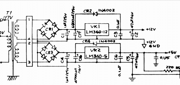
The Commodore 1541 disk drive is a hot and heavy device with a chunky transformer and two linear regulators which create a lot of heat. While it is possible to buy a switch-mode PSU board that provides 12v and 5v DC and remove the transformer, this is a fairly significant deviation from the original implementation and I have decided to try and make as few changes as possible to get it to be useable.
This regulator PCB provides an alternative to the linear regulators and is significantly more efficient. Several versions of this project exist in the wild. This is my take and is designed to be able to be made for the lowest cost using boards partially assembled by JLCPCB with the remainder of the bits coming from LCSC.
This is a work in progress, I don’t have everything perfect. I was hoping to design it so that I could cover the inductor and switches with an RF can of the appropriate size, but that is going to be for version 2. As you can see below the schematic isn’t brain surgery. It is an adaption from a simulated model provided by the TI WEBENCH. If you have a better regulator that can be sourced by LCSC I would love to hear it.
Building
If you wish to construct this device here are the manufacturing files for construction with JLCPCB:
| Version | Gerbers | Positions | BOM |
|---|---|---|---|
| v1.0 | GERBERS | POS | BOM |

